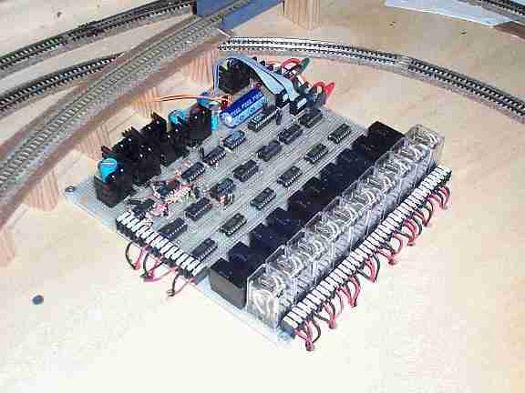
Figure 1 One of my train controller cards wired to my layout
Model trains is a ‘serious’ hobby: which is to say those within the hobby, even the children, seem to devote serious amounts of time and energy and sometimes even serious quantities of money whilst all the time, remembering to have serious fun.
The good thing about the model train hobby is that there are many different ways in which it can be legitimately enjoyed. Some hobbyists favour the modelling and construction aspect, some favour control and scheduling or perhaps even something else, but I think that every model train hobbyist enjoys playing with trains best of all! No matter why they claim to enjoy it, most participants have their own story to tell about how they discovered their interest and I too am one such ‘engineer’. Indeed, this project, an automated computer controlled train set, is part of my story…...
A long time ago when I was a 6 year old boy, I remember Santa bringing me my first train set. On that Christmas morning, I rushed to the lounge room and upon discovering an HO starter set, enthusiastically unpacked and admired it to the tremendous amusement and satisfaction of my parents. Eager to share my joy on that Christmas day, my father and grandfather, provided me with substantial assistance in setting up the modest circle, installing the batteries into the power pack, connecting the wires and setting the shunting engine and its three cars onto the track. They then proceeded to hog control of this, my first "layout", for the remainder of the day - much to the amusement of my mother and grandmother.
Thankfully, my mentors were not train fanatics by any stretch of the imagination and in the coming months and years, I was able to explore my new hobby with somewhat more access to my equipment. But as time progressed, my interest in model trains took a back seat.
In my final year of university, I was fortunate to choose a subject in which the lecturer assessed each student on the basis of an "operating systems" project to automatically schedule two independent locomotives on his computer controllable layout. Needless to say, I’d chosen the right subject and long after I had conquered the programming of his layout, I was still working on my own version of the same thing. That was 15 years ago. It finally took my 3 year old son’s fanatical interest in a certain personified Tank Engine to prompt me to finish it.
To put things in perspective right at the start, the nature of the construction and programming techniques you will require to replicate the design in this series of articles will require you to use a wide range of hobbyist skills. For example, I chose to construct the design on a matrix card (as shown) and my example software is written in "C" for the Linux operating system. This is not a straightforward "build it and use it" project but more of a longer term "build, test, configure, compile, modify and improve it" project – much like the hobby of model trains itself. But regardless of whether you decide to attempt it or not, I hope that simply reading about the background and my design will help bring a new perspective and refound interest in the hobby which so many of us shared as children.
Figure 1 One of my train controller cards wired to my layout
Of course, even if you don’t attempt construction of the circuit, there’s a lot to think about and be applied in other projects in understanding the principles of the electrical design and looking at how the train controller software does its job. If you're interested in using your PC to control complex real world applications for example, the interface circuit concept and its communications software routines could form the basis for a wide range of applications.
This project will be presented in a series of several articles and in this first instalment, we’ll explore the two main methods of controlling multiple trains on a single layout. The next article will investigate the properties of DC motors which are found in most model engines and subsequent articles will present the circuit, construction and testing, configuring the software to work with your layout design and some of the programming concepts if you'd like to modify the software yourself. So, sit back, put on your reading glasses and recall bygone days when you used to play with trains….
The electrical basics of model train sets
There are a large number of different model train systems and standards which have evolved during the more than sixty years that the hobby has been recognised. The different modelling systems are classified by the characteristics of scale rather than electrical differences and many of the scale names are probably familiar to you.
By and large, the two most popular scales are HO and N and depending upon where in the world you live, most of the model train market is centred around the HO scale (1:87) and followed a significant way behind by N scale (1:160). Other scales such as Z, O, S, G and variants of these are also available. In this series, I'll be focusing on HO and N scales but with a little thinking, most of what is covered can be applied to other scales also.
An advantage of the larger scales is that they are more robust. An advantage of HO, apart from there being an enormous variety of products on the market, is that its size lends itself well to the capabilities and dexterity of younger modellers. An advantage of N is that equivalent layouts occupy just a quarter of the space when compared with HO and although the N market is smaller than HO, there is still a good variety and availability of equipment and materials.
As many of you are probably aware, both HO and N scale train sets operate with a nominal 12 Volt DC power supply and when powered at the nominal voltage, the trains travel at their fastest. At "full speed" however, most model trains travel relatively faster than their real life counterparts were ever able to and so to operate a model train at truer to scale speed, less than 12 Volt should normally be required.
Sometimes, it is advantageous to power a train with a waveform other than pure DC. Rectified AC and Pulse Width Modulation (PWM) are two common techniques used instead of pure DC and their merits and disadvantages will be discussed later. Even when waveforms which are not pure DC are used to control conventional HO and N gauge trains, the magnitude of the average voltage must still be in the range 0 Volt to 12 Volt.
I have used the word "magnitude" because in order to operate a model train in reverse, the polarity of the driving voltage needs to be swapped. In simplistic terms, when reversing the voltage, the DC motor in the locomotive turns in the other direction and backs the train up.
This highlights the need for a convention in model locomotive design so that when mixing and matching locomotives on a model layout, they travel in the same direction for the same applied voltage. Indeed, there is such a convention and if you look from behind a model locomotive towards the forward direction, the track on the left should be negative and the track on the right should be positive - at least for the smaller scales. If the track on the left becomes the positive track, the train will travel backwards. Simple!
But through trial and error, I was quick to realise that the electrical aspects of model railroading are by no means simplistic. Sure, if you apply an appropriate voltage to a model train, it moves in one direction or the other and many hobbyists have built themselves impressive and viable layouts without needing to explore the electrical side of the hobby any deeper. But as we shall see as we continue through this series, the electrical aspects of model railroading can be anything but trivial and as electronics hobbyists, we can find a lot more to enjoy in model railroading if we start to investigate and understand some of these details.
I’d like to wager that if you asked a group of train hobbyists to describe their very first layout, the most common response would be "a circle" or "an oval" as shown in Figure 2a. The best thing about wiring such a simple layout is that there is not much scope for making a wiring error. One wire goes to the inner track and the other wire goes to the outer track. The only real potential for a short circuit is through mistake or train wreckage and both of these are usually easily recognised. Of course for the younger hobbyists, an attempt at the latter is often deliberate.
Watching a train circulate on a new trivial layout can hold only so much appeal and sooner or later, most of us have invested in our first sets of points (often called switches or turnouts depending on the country in which you reside). With two sets of points, there are a number of different variations which can be created in the oval but there are traps which can lie hidden in the track work…. there is one simple looking variation which hides a short circuit as shown in Figure 2b. Depending on the brand of points being used, the short circuit might be present or absent, according to which settings the points have been switched. But because this particular layout can never be successful with the potential for a short circuit, it must be removed by cutting the tracks in at least one place.
It is absolutely certain that by making one cut as shown in Figure 2c, the potential for a short on the tracks will be removed but alas, the problem is not so easily solved. When a locomotive crosses from one side of the break to the other, either of two bad things will happen.
Firstly, the locomotive’s metal wheels may recreate the short because the two sides of the gap might be momentarily bridged. Most model train engines use more than one axle to pick up power and each such axle is simply wired in parallel. When the first power collecting axle crosses the gap to the next track section, the leading axle will be on one block and the trailing axle on the previous block. The engine’s internal wiring will unambiguously short the power supply if the track polarity is different in the two sections.
Secondly, even if the locomotive has only one axle with voltage pick up capability (that is if the short circuit will only be momentary as the wheels cross the tiny gaps in the tracks), when the locomotive reaches the other side of the cut it will quickly 'sense' that the polarity of the power on the other side of the break has reversed and so the train will try to change direction and go back to from where it has come! As it is unlikely that it will oscillate to and fro for very long, it will come to rest over the gap and so also indefinitely prolong the short circuit. A better solution is required.
To finally solve this hidden short circuit problem, we must recognise that by inserting a diagonal within the simple oval, we are really creating a way for an anticlockwise moving locomotive to swap to clockwise operation. These are sometimes called "reversing loops" or "reversing passes". In order to change a model train’s direction, the polarity of power on the tracks must also be changed, no matter which way the train is facing. (This is not strictly the case with DCC and we will discuss this later.)
In a simple sense, because it is impossible to reliably swap the polarity on the tracks as the locomotive is precisely above the cut in the tracks, two cuts are required in the layout so that the track is divided into two completely independent sections (called "blocks") as shown in Figure 2d.
Now, if the train is started in an anticlockwise direction on the outer loop, and assuming that the polarity on the diagonal track has been set correctly, the locomotive can be directed onto the diagonal block without stopping it. When the electrical part of the train is completely off the oval block and on the diagonal block, the polarity on the oval can be quickly changed before the train reaches the second set of points. When the engine crosses the second break in the tracks, the polarity will have been set correctly so that the train will move clockwise without further mishap.
Congratulations! You have just understood one of the most important secrets of making successful train set layouts - electrical blocks - and by no coincidence, this is the basic track wiring principle on which this series of articles is based.
The basics of DCC
Before proceeding to talk about building a controller for a larger block based train layout, we should pause to examine an important alternative called DCC which has emerged during the past few years. DCC stands for Digital Command Control and is a computerised protocol for sending strings of directives from a centralised train control point, over the top of the voltage carried by the track wiring and power connections, directly to each train engine and to various peripheral controllers which may be scattered around the layout.
In a DCC system, the voltage which is presented to the track is no longer the nominal 12 Volt DC signal (for HO and N gauge) described earlier. It is an alternating current with a fluctuating frequency of several kHz and approximately looks like a 14 Volt bipolar square wave (meaning a 28 Volt peak to peak waveform centred around zero extending to +14 Volt and –14 Volt. The actual frequency of the signal is changed in order to represent "1s" and "0s" with a "1" being a short +/-/+ transition and a "0" being anything longer (up to a set limit).
The heart of a DCC system is the Command Station. This is usually a stand alone microcomputer with a variety of input devices ranging from throttle controls to simple toggle or push button switches. Sometimes, the Command Station is a peripheral of a Personal Computer so that the PC can be programmed with a train schedule ahead of time and the Command Station controls the trains and the layout to "play out" the schedule. Or perhaps the PC is just a sophisticated manual throttle.
For those who are interested, the data flow from the Command Station takes the form of a string of short packets which are continually replayed in sequence until one of the settings is changed. When a setting changes, the packet sending the former setting is "dequeued" and a new packet specifying the new setting is "enqueued" so that the updated setting is now replicated.
The start of each packet is a header of "all 1s" followed by an address, an instruction and a checksum. Then, the next header for the following packet is sent and so on. Because the packets are indefinitely repeated, if a locomotive or peripheral misses its packet for some reason or another, the command will be resent shortly afterwards so the error will not be apparent.
This has been but a brief explanation of DCC signalling. More detailed explanations can be found at http://www.loystoys.com/how_works.html, http://www.digitrax.com/clinic.htm, and http://jdb.psu.edu/nmra/faq_19.html or in a number of other technical references to DCC.
The Command Station is sometimes accompanied by one or more Boosters. The Booster is just a fancy name for a DCC power supply which multiplexes the DCC signalling protocol onto the power which is supplied to the trains and peripherals. The idea behind separate Boosters is that in large layouts, it becomes impractical to centralise the power distribution because of the resistive losses experienced in the track and wiring. By placing a number of Boosters around the (large) layout, the problem of voltage drop can be minimised by distributing the power centres.
In a DCC system, each locomotive needs to contain an on board Decoder. This is a small circuit board which monitors the track voltage, detects and decodes the DCC signalling, recognises commands specifically addressed to it and acts upon them. As you can imagine, the space which is available within a locomotive is limited and so decoder boards need to be tiny. There are a good variety of HO and N scale DCC Decoders available on the market but particularly in N scale which is an eighth of the volume of HO scale, the size of the decoder and its heat dissipation are very important parameters. DCC is of course also available for other scales.
Whilst the circuit for a Decoder is not overly complex, the miniaturisation of a Decoder is likely to be beyond the capability of most home workshops and is best left to commercial surface mount production. In my case, I am specifically interested in N scale and even more specifically in steam trains. In some (but not all) N scale steam locomotives, it is possible to install the DCC Decoder into the coal tender and then unobtrusively connect wires across to the engine. I would have dearly loved to have designed and built and written about a DCC based system, but alas, once an N scale Tank Engine (like the popular "Thomas", which has no tender), or the tinier N scale engines (such as an 0-4-0, referring to the wheel configuration of the engine) has its DC motor installed, there is insufficient space for a DCC decoder, at least using present technology.
It is sometimes claimed that DCC controllers are able to operate non DCC equipped locomotives and strictly speaking, this is true. Not withstanding strange side effects such as buzzing, we’ll read next month why it is not in fact advisable to operate model trains like this for more than a very short period of time.
So at least in my mind, the DCC approach has not yet been able to resolve the problems I face in controlling my N scale layout. No doubt miniaturisation will improve one day, but that’s not really the point of having started this project!
In order to operate point motors, signals, lights, car decouplers and other such peripherals, a DCC Accessory Decoder is required. In concept, these are similar to the on-train decoders but usually have outputs which are binary (on or off) or momentary / oscillating (on then off).
DCC systems offer a number of nice features such as the ability to regulate the amount of power presented to a locomotive on an engine by engine basis. So the setting required for "half speed" on one train need not be the same setting required to achieve the same actual speed for another. Whilst the project I describe here is also capable of engine by engine control, a DCC system allows you to "double head" two locomotives (also called a "consist") and even though powered through the same track blocks and from the same voltage source, each locomotive can receive individual programming on the basis of its specific characteristics.
The ability to detect and locate an engine is critical if you desire that your layout be controlled automatically from a computer and the DCC system offers no practical assistance at this stage. DCC is mainly a protocol for getting information from a central controller towards its peripherals, not for gathering instantaneous feedback from those peripherals back to the controller. As we shall see later, the simplest way of computer controlling a DCC layout may very well be to create an identical blocked structure to that which we would require for a more traditional block controlled system.
To DCC or to Block Control. That is the Question.
Figure 3 Track block solutions for DCC and conventional layouts
Figure 3a shows a simple layout consisting of a basic figure 8 track, with an outer loop creating a large oval and a single siding. There are seven sets of points in this layout arranged to create the potential for reversing loops. As discussed before, it is necessary to make some cuts into the track so as to remove any potential for short circuits which might arise when the points operate or when trains cross from one block to the next. In this basic layout, there are a couple of ways this can be done but for the purpose of illustration, lets assume that 4 cuts have to be made to create 2 independent power blocks.
This basic DCC layout can now support one, two, three or more independently running locomotives and if you use some imagination, you will see that with some shunting into sidings and alternate route stubs, you can run any of the locomotives on any arbitrary route even if the paths sometimes would coincide. But the more you think about running trains with arbitrary routes, the more you will notice that short circuits will arise whenever a train needs to loop around on itself and travel the same route in the reverse direction.
It is clear that the same layout and same blocking structure shown in Figure 3a would also work for block control. However when using block control, at most one train can be on any block at one time, at least if you want to maintain independent control.
The layout shown in Figure 3a contains only two blocks and you might already have realised that under block control, only a single train could be controlled. For the best controllability in a blocked layout, particularly a computer controlled block layout, there is a tremendous benefit in dividing the layout into a larger number of smaller blocks. So let’s now take a look at how the same layout might be designed for using a block control system.
Figure 3b shows an alternate arrangement which uses the same track shape, the same seven sets of points but this time, there are 13 cuts in the track creating 10 independent blocks. If we chose, we could have installed more cuts to create more blocks, or fewer cuts and had fewer blocks for the same layout. But keep in mind the constraint that no more than a single train can be controlled independently in a single block at the one time. So the more blocks in a layout, the greater the control flexibility, the more potential trains can be run and the greater the operational opportunities.
It may seem that block boundaries can be chosen arbitrarily while keeping in mind that things should be kept as simple as practical for the human who is constructing the layout and will be controlling the trains. When it comes to computer control, you need to remember that the software that will be controlling the train set will be built up of various rule based algorithms and that in order to work, the blocks need to be designed in an orderly way.
I’ll spend time later in the series discussing how the block structure of the layout can be represented in the software but for those who are interested in designing your layouts before then, it will suffice to say that blocks which contain more than one set of points (such as blocks 4, 7, and 2 in Figure 3b) must be arranged so that if a locomotive starts moving from the middle of the block, it will be able to travel towards any of the exits from block without needing to stop and change direction.
Now that an arrangement of blocks has been chosen for the block control method, a decision needs to be made about how many power supplies are needed and how they are going to be connected. In short, a minimum of one power supply is required for each train which is to be operated independently, regardless of the number of blocks. That is, if we want to run two trains on this layout, we will need at least two power supplies. If we want to run three, we will need three power supplies and so on. Of course, in this example, at most ten power supplies will be needed because there are only ten blocks to which they can be connected.
If one power supply is provisioned per train, it will need to be progressively switched from block to block as the train it is powering moves around the layout. On the other hand, if one power supply has been provisioned for each block, the operator will need to progressively reprogram the settings of each power source as the train moves so that when a train moves into the next block, its new power supply smoothly takes over where the last one left off. Humans of course find the first far simpler to manage and this is how manually controlled systems have been operated in most traditional blocked layouts. Computers on the other hand manage either method equally easily and this project uses both techniques.
The design of a layout intended for exclusive DCC operation usually requires fewer cuts in the track because DCC does not rely on having a larger number of electrical blocks in order to control more trains. But even though a DCC layout may not need as many cuts, both DCC and conventional block control share exactly the same potential for short circuits and these must still be avoided by cutting the track and inserting mechanisms to swap the connection of the two power supply wires where trains can loop back on their former route.
It's certain that you can get a basic DCC layout up an running in a day and for most, this is the only justification required to choose this method. It will take considerably longer for you to construct the design described in this series but in the balance, if the goal is to specifically interface a train set to a computer so that the computer can take over some or all of the control responsibility (and as much equipment as possible is to be home-built), DCC is less likely to be your choice. This is not to underestimate the tremendous constructional simplification many hobbyists find invaluable when choosing to use off the shelf DCC modules.
The train controller project is based on the block control method and includes two programmable power sources per card and an arrangement of relays for switching either of the two power sources to any of the blocks. A number of these train controller cards can be connected together to control larger layouts and more trains with greater operational flexibility.
With this approach, the controlling computer needs to make the appropriate relay settings as the trains move around the layout and if there is more than one train controller card, reprogramme the power supplies as each train moves from the domain of one controller card to another.
But what does it mean to "automatically control" a train set?
Although we won't start to look at an example train controller programme until later in this series, I expect that curiosity will start to get the better of you well before that time! So to at least partially satisfy the inevitable questions you may be already thinking, I will finish off the first article with a very basic description of the way I use the train controller with my train set.
In designing the circuit and writing my own controller software, my objective was to be able to define a number of independent "routes" for each of my trains on my layout. Ideally, when I ran my layout, I wanted the computer to read these "route files" and control the power supplies and point settings on the layout so that each of the trains more or less followed the paths which had been defined. Indeed, this is what my train controller software attempts to do.
For the train set layout shown in Figure 3b, a simple route file might look as follows:
* route1.txt
* This is a route file used
by the train programme.
*
* A route is specified by listing
block numbers in the order that they should
* be visited.
*
* LEGAL LINE FORMATS:
* [positive integer] [0.0 <
fraction <= 1.0] {comment}
* or
* [positive integer] {comment}
* or
* {comment}
*
* The positive integer represents
the next block to visit.
* When present, the fraction
represents the speed (as a proportion of full speed) to use.
* Comments are optional. Blank
lines are also legal.
*
* Apart from the route having
to be contiguous (blocks actually connect to
* each other in the sequence
listed), the same block can appear in the route
* as many times as desired.
*
* At the end of the route, the
train programme will restart from the beginning
* and so it is expected that
the last block number in this file joins onto
* the first block number in
the file. If not, the train programme will exit
* with an error.
1 .7 * this is the first block
in the route, use a speed of 0.7*FULL SPEED
2 * this is the second block
in the route and connects with the first
3 * this is the third block
in the route and connects with the second
4
5
7 .85 * increase speed marginally
9
2
6 .33 * decrease speed
7
8
4 * This is the last block in
the route and connects with the first
In order to control two or more trains on the layout at the same time, the train controller software uses different route files for each train. Actually, you could choose to use the same route file for all trains (so that all trains follow each other around the same route) or you could define completely independent routes for each of the trains.
If you think carefully about controlling trains using arbitrary routes, you will realise that stand off situations could easily arise. When two trains are being controlled for example, if the second route was defined as the same path as the first route except in the OPPOSITE direction, the two trains would travel until they reached a point where they were facing each other and both wanting to move forwards. In this case, the software needs to be clever enough recognise that there is about to be a deadlock and it needs to avoid the stand off by slightly delaying one of the trains or by making a slight variation to one of the routes to enable the other train to pass. If you’re thinking of constructing the train controller circuit, you might like also like to think about how you might write a controller programme.
Alas, there is much more to be said about the project
and its software, but now is not the time! You are of course invited to
follow this series in the coming months and if you are so inclined, to
construct the circuit for yourselves. Until then, welcome (or welcome back)
to the hobby of model trains!
Stefan Keller-Tuberg BE (Hons) MEM
Stefan Keller-Tuberg is a professional engineer with
an honours degree in Electrical Engineering from the University of New
South Wales and a masters degree in Engineering Management from the University
of Technology, Sydney. He and his family are presently living in the United
States where Stefan works in the telecommunications industry planning service
architectures and product evolutions for high speed xDSL and Optical Internet
access products. They are enjoying life in the USA but are looking forward
to their return to Australia some time in the coming year.
Copyright 2001. Stefan Keller-Tuberg.