Introduction
Planning the drive
Building the rocker box and bearings
Building the ground board and bearings
Distortion of the wheels by the motor and stepper shafts
When using my design with a Kriege style Dobsonian...
Now that I have finished building the telescope
During the process of planning the construction of my Dobsonian telescope, I looked around for information published by others describing how to motorise a telescope. In all the categories, there were several basic approaches but I didn't really want to try any of these on my own motorised telescope.
In the end, I thought long and hard and came up with the approach shown on this page. It's straightforward and uses roller skate wheels in the rocker box and roller blade wheels on the ground board.
The basic idea is that when you motorise your telescope, you want to come up with a bearing which offers almost no friction but which is durable, reliable, accurate and lends itself to being driven by a motor shaft. This is in contrast with a traditional Dobsonian telescope bearing which needs to provide a controlled amount of friction to stop the telescope swaying around. The reason a motorised telescope bearing does not need to provide friction is that the motors themselves will lock the telescope where it's supposed to be pointing (because a powered motor's shaft tends to "lock" into position in lieu of bearing friction).
When I looked around at how other amateur telescope makers had implemented their drive train, I saw that most had chosen to use a geared approach. Typically, a DC or stepper motor is used to drive some form of gearbox or geared teeth built onto the alt/az bearings and the bearings themselves are formed often from either teflon pads or small metal ball bearings as found in roller skate wheels. A common comment seems to be that the gears introduce backlash and some eccentricity which leads to some telescope pointing inaccuracy. Software often attempts to compensate for these problems.
I also saw some telescope makers attempting to build friction drives to get around the backlash problem. It struck me that this might be an interesting approach for my own telescope and so I set to thinking about how I might do this.
After some toying with different ideas, I decided that I'd base my own design on roller skate and roller blade wheels and that I'd directly drive one of the alt wheels and one of the az wheels with my two stepper motors.
I chose to use four roller skate wheels for the altitude bearings because roller skate wheels are flat and the altitude bearings in a Kriege style Dobsonian have flat semi-circular surfaces. For the azimuth bearings, I chose to use three roller blade wheels because their profile is pointed, not flat. The wheels used in the azimuth bearing are mounted perpendicular to the direction of bearing rotation and thus the contacting area between the roller bearings and the bottom of the rocker box should be minimised to avoid rubbing. Roller blade wheels do this much better than a roller skate wheel because they are pointed.
Before describing how I built the rocker box, let's take a look at the bearing.
|
|
|
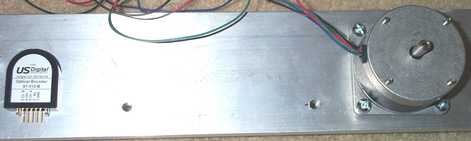
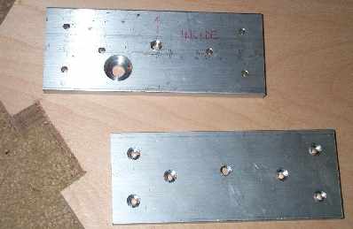
In order to maximise strength of the bearings, I chose to mount them on lengths of aluminium flat stock. I didn't want to skimp on strength so I used a thickness of 3/8 inch (10mm) and a height of 3 inches (76mm). One of the two aluminium plates also accommodates the stepper motor and shaft encoder.
I positioned the wheels so that the angle formed from the centre of the altitude bearing towards the point of contact with the roller skate wheels was 65 degrees. Then on one of the two plates, I drilled mounting holes for the stepper motor and the shaft encoder. I positioned the shafts of both the stepper motor and shaft encoder a little below centre so that any flexure in the wheel axles would tend to increase the pressure on the shafts rather than reduce it. As it turns out, there is basically very little flexure. :-)
The accuracy of the plates is very important. The holes for the axles must be precisely in the same position on each of the two plates and the position of the two plates on the rocker box must also be identical on both sides of the box. The only way to really ensure this is to make the plates at the same time as you're making the rocker box.
|
|
|
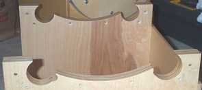
The finished rocker box (without and with the plates) looks as shown in the pictures above and is a variation of the Kriege style rocker box.
The sides of the rocker box which will carry the bearings are made of laminated plywood and I sized mine to be a little thicker than the thickness of the semicircular telescope bearings. As I used 25mm (1 inch) side bearings on the telescope, I made the sides of the rocker box 32mm (1 1/4 inch) thick by laminating two half inch plywoods and a quarter inch plywood.
When I had the two side blanks, I screwed them very firmly together using drywall screws, being careful to put the screw holes in the "hole" sections I was going to later route and cut out. By screwing the two rocker box sides together like this, I was able to cut them perfectly square using a table saw so that they were precisely alike.
Keeping the two sides still firmly screwed together, I prepared the two aluminium flat blanks which were going to become the bearing plates. Firstly, I used a table saw to cut two lengths to precisely the length of my rocker box, then I clamped the two pieces to my sandwich of rocker box sides. Now that I had the aluminium positioned precisely over the timber sides, I used a drill press to cut pilot holes for the roller skate wheel axles and an additional six pilot holes for the screws which would hold the plates to the sides of the rocker box. Because I drilled all holes at the same time while the aluminium was clamped to the timber, I ensured that the holes were all precisely aligned.
Now I drilled out the screw holes in each piece of aluminium and timber and I used a hole saw to cut the timber to accommodate the roller skate wheels. I used a 5/16 inch (8mm) tap to cut threads for the roller skate wheel bearings and a 1/4 inch tap to cut threads for the six screws that hold the plate to the timber.
On one of the two plates, I needed to drill some additional holes for the stepper motor and for the shaft encoder. Because the shaft encoder I chose only had about 1/4 inch (6.5mm) of thread and my plate was 3/8 inch thick, I needed to bore a flat bottomed hole into the inside surface of the plate. I used a 3/4 inch Forstner drill bit that I didn't mind abusing a little and, with my drill press, created a perfect flat bottomed hole. I needed to achieve the depth little by little and clean the drill bit of the aluminium shavings at regular intervals. It took approximately 1 minute of gentle drilling to achieve a depth of about 5 mm. There's a picture below of one of my ground board plates with the shaft encoder hole bored out. Using a Forstner bit in this manner works remarkably well. Apologies to all the fine carpenters out there.
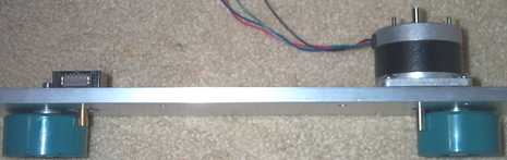
The diagram above shows what the plates look like when assembled onto the rocker box.
A final note about the roller skate wheels themselves. Roller skate wheels come in various thicknesses and you might find, as I did, that the wheels you purchase will be too thick for your telescope. In this case, the remedy is simple: sand the wheels back to an acceptable thickness. I ended up removing about 5mm from the edge of my wheels using a bench sander. The process is quick and accurate but you end up with piles of plastic dust :-).
The ground board is a little simpler than the rocker box but the plates look surprisingly similar.
In my look around the Internet and library searching for examples of other motorised Dobsonians, I did not come across a single implementation which used a ground board as thick as mine. I chose to make a very thick ground board because I could easily saw square edges with a table saw but I couldn't easily construct solid right angle mounted plates for holding the stepper motor, roller skate wheels and shaft encoder to a thinner ground board. The thicker ground board allowed me to use flat stock for the plates which could then be simply screwed to the side of the thick ground board. Although I now have the thickest ground board in the universe for a 12.5 inch Dob, the important thing is that the idea is simple and it works very well.
I made the ground board out of three triangular pieces of 3/4 inch (19mm) plywood. When glued together, the total thickness is 2 1/4 inch (57mm). Somewhat of an overkill when it comes to strength for your 12.5 inch Dob, but there's certainly no flexure in it. :-)
|
|
|
In the diagram, you can see that the three corners of the triangular ground board have been cut off to accommodate the plates and roller blade wheels. One of the three plates is also the home for the stepper motor, the second is also the home for the shaft encoder and the third just has the wheel.
Constructing the plates is a similar process to that described above. You don't have to be quite so accurate as for the rocker box because there are only three points of contact between the rocker box and the ground board (the three wheels) and no matter how inaccurate you place the wheels, the telescope won't rock. Having said this, it's still a good idea to try to do your best when it comes to accuracy.
Hockey pucks make great ground board feet when you drill them out and recess the hole to accept a bolt.
As for the rocker box, you need to drill / route / saw out holes to accommodate the roller blade wheels. When assembled, the plates mount flush with the edge of the ground board and the wheels sit in the hole that you've cut out.
Instead of machine head screws to hold the plates in place on the ground board, I chose to use the longest drywall screws I could find. Unlike the rocker box, there's nothing for your screws to hold onto other than the wood itself and long drywall screws make good anchors.
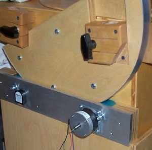
When it comes to making an azimuth bearing, if you follow the instructions in Kriege's book, you will need to purchase a hefty nut and bolt. I chose a 3/4 inch diameter 4 inch long bolt. The nut must be welded squarely onto a small steel flat and the welded assembly then screwed to the underside of the ground board.
Because my ground board was so thick, I was able to hide the nut within the ground board. I bored a shallow 1.25 inch hole into the underside of the ground board, barely large enough to accommodate the entire 3/4 inch nut. When the nut / plate assembly was mounted to the ground board, I placed the nut on the top side, buried within the ground board itself, hidden on the other side of the plate. This, I guess, is one of the other advantages of having such a thick ground board.
I'll be willing to bet that some of you are going to be wary about the accuracy of roller skate or blade wheel bearings used in friction drives. I was also wary because I thought that the constant pressure of the motor and encoder shafts into the side of the wheel would leave lasting impressions which would detract from the accuracy of the bearing. The problem, I thought, might be worst if you leave the telescope untouched for perhaps weeks so that the shaft of the motor or encoder presses against the same place on the wheel for an extended period. In the same way, if the weight of the mirror box presses down upon the wheels in the altitude bearings or the combined weight of the mirror box and rocker box presses down upon the wheels in the azimuth bearings, there may be additional impressions left in the rubber.
As it turns out, the impressions are not lasting: at least on the wheels I chose to use.
Soon after I'd first assembled my bearings, I took the family on holidays and left the telescope at home, awaiting my return. Two weeks later, I returned home and headed straight for the telescope. I found that minor indentations had formed on all wheels which I could feel if I rotated the indentation back and forth past the motor or encoder shaft. For a few minutes, I was a little concerned that this was now the end of my first set of wheels but, to my surprise, when I checked again in about 30 minutes, the impressions had completely disappeared.
To be sure, I am now careful to insert a piece of timber into the bottom of the rocker box so that when the mirror box is stored in the rocker box, the mirror box is spaced away from the altitude bearing wheels. Similarly, I insert a spacers between the rocker box and ground board. Finally, I try to manually rotate the wheels which have shafts pressing against them at least once a week. This last piece of paranoia is probably not necessary, but it certainly doesn't hurt: all of the wheels seem still to be healthy and without lasting impressions.
There are a couple of things to watch out for when implementing the roller-bearing design I've described above.
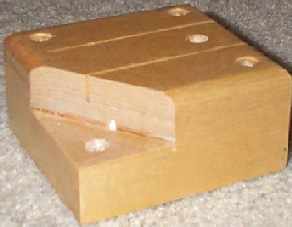
Firstly, a Kriege style Dobsonian has eight very nice looking pole-block housings screwed to the side of the mirror box. These are the almost square blocks into which the eight aluminium poles of the truss plug. In the classical design described in Kriege's book, the side of the rocker box has two semi circular cut-outs on which the mirror box bearing slides. As the mirror box rotates on this bearing, the leading pole-block on either side of the telescope rotates through the semi-circular cut out and protrudes beyond the side of the rocker box.
In the bearing design I have proposed, two hefty aluminium plates are bolted to the sides of these semi-circular cut outs. As the leading pole-block rotates downwards, I found that they happened to hit the aluminium plate at about 45 degrees of altitude. This meant that I could only see the part of the sky between 45 degrees and zenith - not really satisfactory. I modified the two leading pole blocks by cutting a small triangle from their fouling corners as shown in the picture below and the telescope now tilts down to about 20 degrees comfortably. If I'd cut a slightly larger corner of the pole blocks, I could have allowed the telescope to rotate a full 90 degrees in altitude however, this is a Dobsonian telescope and looking at objects near the horizon is not comfortable! (Picture yourself on your hands and knees, shuffling around in the dirt in the pitch darkness.)
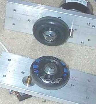
Secondly, I assembled the three roller blade wheels onto the aluminium plates that will reside on the ground board. Whilst they assembled fine and operate without problem, I did notice a problem on one of the plates: the plate which also holds the stepper motor.
Roller blade wheels seem to be manufactured in an injection mould which leaves a very slight raised bump around the circumference of the wheel. This very slight bump happens to significantly reduce the area of contact between the shaft of the stepper motor and the wheel material and thus, the friction between the wheel and motor shaft is also reduced. I was not able to get a good enough contact to avoid slipping.
To resolve the problem, I carefully removed the bump using my bench sander and gently rotating the wheels at 45 degrees to the motion of the belt. This seems to have fixed slippage once and for all.
As a further note on this problem, the shaft encoder, which also has the same type of arrangement as the stepper motor and roller blade wheel, does not show the same slipping problem. I expect that this is fully because the shaft in the shaft encoder requires almost no torque to turn it and so not much friction is required between its shaft and the roller blade wheel.
Because the shaft encoder will work OK, the computer which controls the telescope will always receive accurate feedback about the telescope's movements and so strictly speaking, it shouldn't matter too much if the stepper motor slips a little. I'd rather fix the problem however and certainly, it would be best if it is corrected on the shaft encoder's wheel also.
Now that the telescope is built, I can comment that the motion of the telescope feels something like sliding on floorboards in socks. (What a poor analogy?). When the motors are unpowered, they still provide some resistance to being turned. You can imagine that the combined feel of roller skate wheels retarded by stepper motors feels like something very closely resembling a "traditional" dob sliding on teflon and "ebony star" bearings. It is like the roller skate wheels have brakes on. So even when the telescope is not being controlled by a computer, it is fully useable as any other regular dobsonian would be.
When I apply power to the stepper drivers and they pass current through the windings of the steppers, the motors lock into position almost completely securely. It is very difficult to manually rotate such a "locked" stepper motor shaft. When bumping the telescope in this condition, you are met with quite substantial resistance. If you keep pushing, the aluminium bearing surfaces will slide very reluctantly over the motor-locked roller skate / blade wheels. But the good thing is that the wheels providing the mechanical linkage to the shaft encoders never slide because they are always free to rotate. This means that the shaft encoders will faithfully register the error caused by the bump and the software can wind back the steppers to compensate!
If you find that the unpowered telescope is still too free to move around and the wind blows it or it doesn't feel as though there's enough friction when you're manually positioning it, there is a simple fix. Measure the resistance of the stepper motor coils and place a half watt, approximately equivalent value resistor across each of the coils. When you try to rotate the shaft of the stepper motors now, they will feel as though they're braked! Reducing the resistance further will increase the breaking until they start to feel as though they're locked. In the extreme, directly shorting the windings out will make it seem as if the motors were actually powered and locked. However, when you do power the motors, remember to remove these resistors. You might otherwise start to smell them!